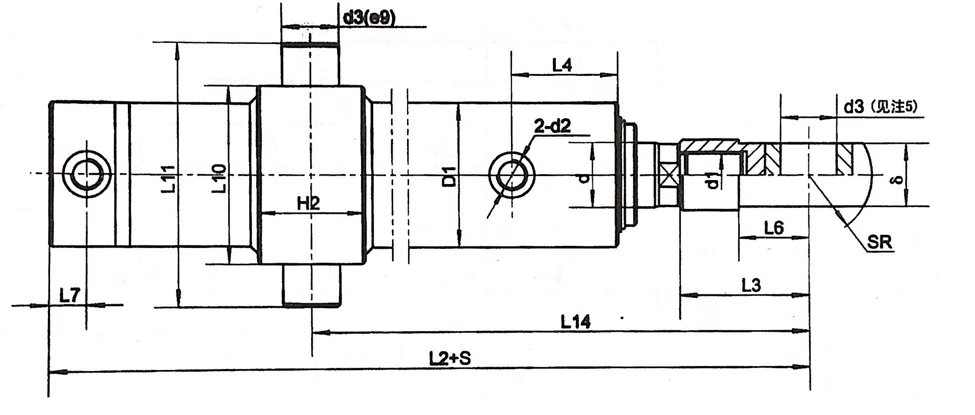
YX02HSG K 01 - D/d E - ① ② ③ ④ - S
| Symbol | Implication |
| YX02HSG | Yongxiang Double-acting Single Piston Engineering Hydraulic Cylinder |
| K | Rod Cover Fixing Structure: 1. Thread ( dia ≤φ80 ) 2. K Latch ( dia ≥φ80, no latch for 80/55) |
| 01 | Design No. 01 |
| D/d | Rod Dia / Piston Dia |
| E | Rated Pressure ≤ 16MPa |
| ① | Connection Symbol of Rod Head and Body |
| ② | Connection Symbol of Piston End |
| ③ | Connection Symbol of Oil Port |
| ④ | Buffer Position |
| S | Stroke (mm) |
| Symbol | Connection | Remark |
| 1 | Piston end male thread | |
| 2 | Piston end female thread | Dia ≥63 |
| 3 | Piston end male thread, earring with bushing | |
| 4 | Piston end female thread, earring with bushing | Dia ≥63 |
| 5 | Piston end male thread,earring with spherical plain bearing | |
| 6 | Piston end female thread,earring with spherical plain bearing | Dia ≥63 |
| 7 | Integral piston, earring with bushing |
Only for Dia:40 & 50 |
| 8 | Integral piston, earring with spherical plain bearing |
| Symbol | Position | Remark |
| 0 | No buffer | For rodφ40, 50, 60 cylinder |
| 1 | Two end sides | Rod φ 80-250 Speed ratio=2, Rod end buffer only |
| 2 | Rod end | |
| 3 | Piston head |
| Symbol | Connection |
| 1 | Earring with bushing |
| 2 | Earring with spherical plain bearing |
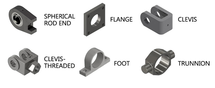
| 3 | Hinged shaft |
| 4 | Rod end flange |
| 5 | Central flange |
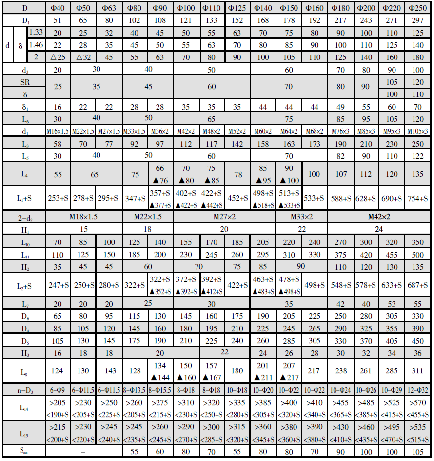
| Model# | Rod Did: D(mm) | Speed Ratio φ | Min Stroke (mm) | Min Stroke (mm) for hinged shaft and flange connection | |||||
| 1.33 | 1.46 | 2 | |||||||
| Piston dia d(mm) | Max Stroke S (mm) | Piston dia d(mm) | Max Stroke S (mm) | Piston dia d(mm) | Max Stroke S (mm) | ||||
| YX02HSGL01-40/dE | 40 | 20 | 320 | 22 | 400 | 25 | 480 | - | 30 |
| YX02HSGL01-50/dE | 50 | 25 | 400 | 28 | 500 | 32 | 600 | - | 35 |
| YX02HSGL01-63/dE | 63 | 32 | 500 | 35 | 630 | 45 | 750 | - | 35 |
| YX02HSGL01-80/dE | 80 | 40 | 640 | 45 | 800 | 55 | 950 | - | 55 |
| YX02HSGL01-80/dE | 80 | 40 | 640 | 45 | 800 | - | - | 30 | 55 |
| YX02HSGL01-90/dE | 90 | 45 | 720 | 50 | 900 | 63 | 1080 | 40 | 60 |
| YX02HSGL01-100/dE | 100 | 50 | 800 | 55 | 1000 | 70 | 1200 | 40 | 80 |
| YX02HSGL01-110/dE | 110 | 55 | 880 | 63 | 1100 | 80 | 1320 | 40 | 70 |
| YX02HSGL01-125/dE | 125 | 63 | 1000 | 70 | 1250 | 90 | 1500 | 35 | 55 |
| YX02HSGL01-140/dE | 140 | 70 | 1120 | 80 | 1400 | 100 | 1680 | 45 | 80 |
| YX02HSGL01-150/dE | 150 | 75 | 1200 | 85 | 1500 | 105 | 1800 | 50 | 80 |
| YX02HSGL01-160/dE | 160 | 80 | 1280 | 90 | 1600 | 110 | 1900 | 40 | 70 |
| YX02HSGL01-180/dE | 180 | 90 | 1450 | 100 | 1800 | 125 | 2150 | 45 | 90 |
| YX02HSGL01-200/dE | 200 | 100 | 1600 | 110 | 2000 | 140 | 2400 | 45 | 100 |
| YX02HSGL01-220/dE | 220 | 110 | 1760 | 125 | 2200 | 160 | 2640 | 50 | 100 |
| YX02HSGL01-250/dE | 250 | 125 | 2000 | 140 | 2500 | 180 | 3000 | 55 | 105 |
Remarks:
- ▲ Only for φ=2 Cylinder 2. △ Only for φ=1.7 Cylinder
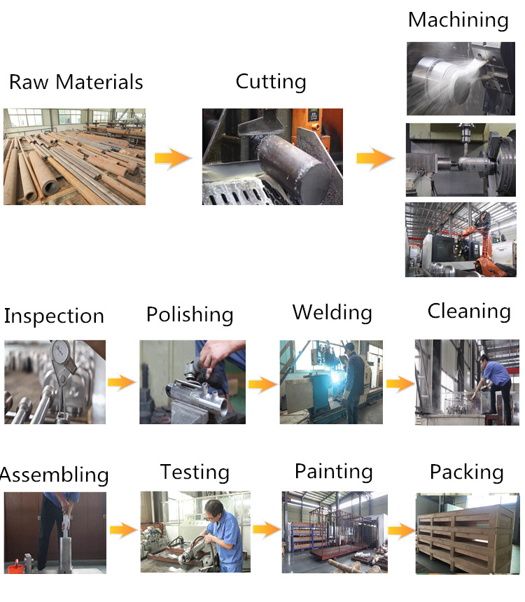
 Produsction and Inspection Process
 Company Certificates
  Q1: Are you a trading company or manufacturer? A1: We are the manufacturer with Exporting License. Q2: How long have you been in the Hydraulic Cylinder industry? A2: Since 2005 Q3: How long is your warranty period? A3: 12 months after on board. Q4: How long does it take to process customized orders? A4: It usually takes 30-45 days to process. It can be discussed. Q5: Have you been exported overseas? A5: We have been exporting to the USA, Canada, Japan, Russia, etc. If possible, when contact with us, please apply information as below
 | Bore | Rod | Stroke | Work Pressure | Mounting | Work environment |
